This is the notes for Introduction to Operating Systems, offered by Udacity.
- Introduction to Operating System
- Process and Process Management
- Threads and Concurrency
- Thread Design Considerations
- Scheduling
- Memory Management
- Inter-Process Communication
- Synchronization Constructs
- I/O Management
- Virtualization
- Remote Procedure Calls
- Distributed File System
- Distributed Shared Memory
- Data Center Technologies
Introduction to Operating System
OS abstracts and arbitrates the computer hardware.
- have direct privileged access to the underlying hardware;
- hide hardware complexity;
- resource management;
- provide isolation & protection between different processes.
OS abstraction: process, thread, file, socket, memory page.
OS mechanisms: create, schedule, open, write, allocate.
OS policies: least-recently-used, earliest deadline first, etc..
OS design principles
- Separation of mechanism and policy (implement flexible mechanisms to support many policies).
- Optimize for common case.
OS protection boundary
Privilege mode in kernel mode has direct access to hardware. User-kernel switch is supported by modern hardware. For example, there is a privilege bit in CPU and can be set by OS. If it is set in user mode, trap instructions are triggered and CPU is switched to privileged mode to allow OS to check whether this privileged access is allowed.
User level application can request OS to perform some privileged operation for them such as mmap (allocate memory). This is system call. It will involve mode change from user -> kernel -> user, and context switch requires saving state for user mode, swapping hardware cache, and executing a number of instructions.
In short, user/kernel switch is not cheap.
OS services are made available via system calls. Examples of OS services:
- Process control
- File manipulation
- Device manipulation
- Information maintenance
- Communication
- Protection
OS type
- Monolithic OS: one piece OS that contains everything
- Modular OS (Linux): more common. OS requires a certain interface that any modules should implement
- Microkernel: very basic kernel with only address space and threads. Everything else, like file system and disk driver, runs out of kernel as user processes. It requires a lot of inter-process interaction.
Process and Process Management
Process: instance of an executing program, similar to “task”, “job”.
- State of execution: program counter, stack.
- parts & temporary holding area: data.
- May require special hardware: I/O.
Application v.s. process:
- Application is static, stored in memory.
- Process is dynamic, a representative of an running application.
Address space, represented from \(V_0\) to \(V_{max}\) (virtual address), is used to represent the “in-memory” state of a process. Address space of a process is divided into:
- Text and data: static state when process first loads. It starts from \(V_0\).
- Heap: dynamically created during execution. It is after text and data.
- Stack: LIFO queue, grows from \(V_{max}\) downwards.
Page tables map virtual address to physical address located in the physical memory.
Process Execution State
The OS maintains a Process Control Block (PCB). It is a data structure that OS maintains for every process.
- Process state
- Process number
- Program counter (PC): at which point the program is being executed. It is maintained in the CPU register.
- Registers
- Memory limits
- List of open files
- Priority
- Signal mask
- CPU scheduling info
- Stack pointer: represents the top of the stack
- others
PCB is created when process is created. Certain fields are updated when process state changes, but other fields change too frequently (like PC). CPU has a PC register that holds the PC for the current running process. It is the OS’s job to update PC in its PCB when a process is no longer running on the CPU.
Context Switch
Switching the CPU from the context of one process to the context of another.
Context switch is expensive:
- Direct costs: number of cycles for load & store PCB;
- Indirect costs: cold cache that leads to cache misses.
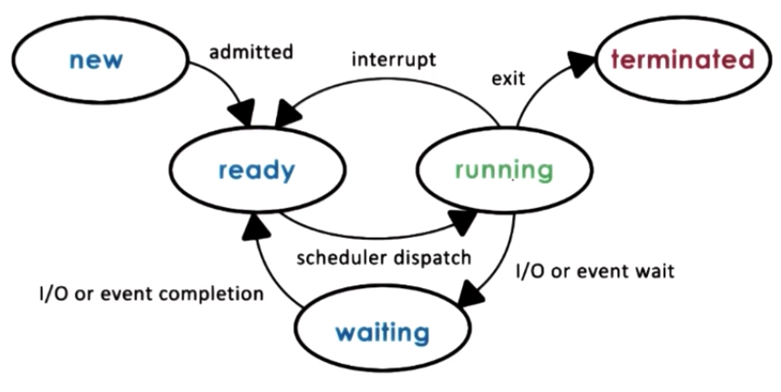
Process Lifecycle
Processes can be running or idle (ready). Scheduler can dispatch it to CPU so it becomes running, and running processes can be interrupted. Process lifecycle is shows as follows:
Process can create other processes, forming a tree of processes. Process is created by fork or exec:
- Fork: copies the parent PCB into new child PCB. Child continues execution at instruction after fork (PC is copied into child PCB).
- Exec: create a new PCB and load a new program and start from first instruction.
On UNIX-based OSs, init is the “parent of all processes”.
On the Android OS, zygote is the parent of all app processes.
Scheduler
A CPU scheduler determines which one of the currently ready processes will be dispatched to the CPU to start running, and how long it should run for.
- Preempt: interrupt and save the current context;
- Schedule: run scheduler to choose the next process;
- Dispatch: dispatch the chosen process and switch into its context.
Efficiency:
\[\eta_{CPU}=\frac{T_{processing}}{T}=\frac{T_{process}}{T_{process}+T_{scheduler}}\]Scheduler design questions:
- What are appropriate timeslice (\(T_{process}\)) values?
- Metrics to choose next process to run?
Inter Process Communication (IPC)
- Transfer data/info between address spaces
- Maintain protection and isolation
- Provide flexibility and performance
Message-passing IPC: OS provides and maintains communication channel, like a shared buffer. Processes write (send) or read (recv) message to/from the channel. +: OS managed -: overhead
Shared memory IPC: OS establishes a shared channel and maps it into each process address space. Processes directly read/write from this memory. +: OS is out of the way -: re-implement code to use the shared memory in the correct way, and set up for shared memory can be expensive
Threads and Concurrency
A process is defined by a PCB. Threads in the same process share the same code, data, and files, but they execute different pieces of the program, so each one of them has its own registers (such as PC) and stack. Thus, PCB for multi-threaded application is more complex. It has shared data, and per-thread exec context.
Threads provide the following benefits:
- Parallelization: speed up the application;
- Specialization: each thread dedicates to a small task, so its easy to manage, and cache efficiency can be improved;
- Compared to multi-processes application, multi-threaded application is more memory efficient, and inter-thread communication is much more efficient than inter-process alternatives.
- Context switch for threads is quicker than that for processes.
- Multi-threaded OS can run execution contexts for multiple processes at the same time, and run OS-level services like daemons and drivers concurrently, on multi-processor hardware.
Thread Mechanisms
Creation
Three key abstractions: thread type, fork, and join.
Thread type:
- ID
- PC
- SP (stack pointer)
- registers, stack, attributes
fork(proc, args) creates a new thread. PC points to the beginning of the procedure proc, and args are copied into its stack. It is NOT the unix fork, which is used to create new process.
join(thread) terminates a (child) thread.
Mutual Exclusion
mutex is a lock used for shared memory area. At any time, only one thread can acquire the mutex, and others must wait on acquiring mutex. The protected part of program is called critical section.
The specification of mutex doesn’t guarantee the order of access granted for pending requests in its queue.
Condition Variable
Some threads wait on a certain condition to be true, while others send a signal when such condition is changed.
- Condition: a type
wait(mutex, condition): blocks a thread’s execution until condition is met. The mutex is automatically released and re-acquired when entering and exiting waitsignal(condition): notify only one thread waiting on the conditionbroadcast(condition): notify all waiting threads
Conditional Variable contains:
- reference to the mutex
- waiting threads
- (others)
Readers/Writer Problem
There is a shared resource. 0 or more Readers can access it at any time, but only 0 or 1 Writer can access it.
A mutex around the shared resource is OK, but it does not allow multiple readers to access at the same time.
Solution: resource counter
- free: resource_counter = 0
- reading: resource_counter > 0
- writing: resource_counter = -1
Resource counter is a proxy to the actual resource. Instead of controlling the resource, the resource counter is controlled through a proxy (i.e. transform multiple states into a state variable guarded by a single mutex).
The code block becomes:
// ENTER CRITICAL SECTION
perform_critical_operation
// EXIT CRITICAL SECTION
A piece of critical section code is executed when entering and exiting the actual critical section. But the actual critical operation is not locked.
// ENTER CRITICAL SECTION
Lock(mutex) {
	while(!predicate_for_access)
		wait(mutex, cond_var)
	update_predicate
} // unlock

// Execute the actual critical section

// EXIT CRITICAL SECTION
Lock(mutex) {
	update predicate
	signal/broadcast(cond_var)
}
Critical section shares the following structure:
Lock(mutex) {
	while(!predicate_indicating_access_ok)
		wait(mutex, cond_var)
	update state => update predicate
	signal and/or broadcast(cond_var_with_correct_waiting_threads)
} // unlock
Deadlock
Two or more competing threads are waiting on each other to complete, but none of them ever do.
A cycle in the wait graph is necessary and sufficient for a deadlock to occur. Edges in wait graph is from thread waiting on a resource to thread owning a resource.
Kernel v.s. User-Level Threads
User-level threads must be associated with Kernel-level threads in order to execute. Kernel level scheduler schedules kernel-level threads onto the actual CPU.
There are multiple Relationship models between Kernel and User-Level threads.
One-to-One Model
User-level threads are directly mapped to kernel-level threads.
Pros:
- OS sees and understands user level threads;
- User-level threads can benefit from native support of thread functionalities such as synchronization and blocking.
Cons:
- All thread management must go to OS (may be expensive);
- OS may have limits on thread number and policies for thread management;
- Application may not be ported to OS with limited thread management.
Many-to-One Model
All threads of a process are mapped onto a single kernel-level threads. There is a user-level thread management library to manage threads in this process.
Pros:
- Totally portable, independent to OS;
- Fewer user-kernel switch.
Cons:
- OS has no insights into application needs;
- OS may block the entire process if one user-level thread blocks on I/O.
Many-to-Many Model
Some threads are mapped to single kernel threads, and others are mapped to their own kernel level threads.
Pros:
- Get the best of both worlds;
- Can have bound (one-to-one) or unbound threads. Bound threads have better responsive time.
Cons:
- Requires coordination between user- and kernel-level thread managers.
Multithreading Scope
- Process scope: user-level library manages threads within a single process;
- System scope: system-wide thread management by OS-level thread managers.
Multithreading Pattern
Boss/Worker Pattern
One boss threads and a number of worker threads.
- Boss: assigns work to workers
- Worker: performs entire task
Throughput is limited by boss thread.
Boss assigns work by:
- Directly signalizing specific worker
- Pros: workers don’t need to synchronize
- Cons: Boss must tract what each worker is doing; throughput will go down
- Preferred: Place work in producer/consumer queue
- Pros: boss doesn’t need to know details about workers; higher throughput
- Cons: queue synchronization
How many workers?
- On demand (high overhead), not recommended
- Static pool of workers
- Dynamic pool of workers, adjusted by 1 at most
Pros: simplicity Cons:
- Thread pool management (and task queue)
- Locality (workers will be more efficient to work on similar tasks): can be achieved with specialized workers
Pipeline Pattern
Tasks are divided into subtasks. Threads are assigned one subtask in the system, so entire tasks is not a pipeline of threads.
Multiple tasks run concurrently in the system, and in different pipeline stages.
Its throughput is the weakest subtask. So we can use a thread pool for each pipeline stage, so that each state can process the same number of tasks within a period of time.
Between stages, communication is done via shared buffer, such as queue.
Pros: specialization and locality Cons: balancing and synchronization overheads
Layered Pattern
Each layer is a group of related subtasks, and end-to-end task must pass through all layers. It’s less fine-grained than the pipeline model.
Case Study: PThread
PThread = POSIX Thread (POSIX = Portable Operating System Interface)
Compilation
Require
#include <pthread.h>
Compile with -lpthread or -pthread:
gcc -o main main.c -lpthread
PThread Creation
- Thread type:
pthread_tis a data structure. - Fork:
int pthread_create(pthread_t * thread, const pthread_attr_t * attr, void * (*start_routine)(void *), void (*.arg));Thestart_routineis the execution (likeproc),argis the argument list.pthread_attr_tis to specify certain attributes of the thread. It returns the status code to indicate whether the creation is successful. - Join:
int pthread_join(pthread_t thread, void ** status). It returns the status code as well.
Pthread attributes:
- stack size
- scheduling policy
- priority
- inheritance
- joinable
- system/process scope
They have default behavior with NULL in pthread_create.
There are int pthread_attr_init(pthread_attr_t * attr);, int pthread_attr_destory(pthread_attr_t *attr); methods to create and destroy pthread attribute, and pthread_attr-{set/get}(attribute) as setters/getters.
Joinable: default to be joinable, meaning the parent thread cannot be terminated before its children threads joined, otherwise these children threads become zombies. If set to false, the child thread becomes detached threads that can run on its own. PThread provides methods to detach a thread after creation, or create detached threads at creation time.
PThread Mutexes
Mutex type: pthread_mutex_t
// explicit lock
int pthread_mutex_lock(pthread_mutex_t *mutex);
// explicit unlock
int pthread_mutex_unlock(pthread_mutex_t *mutex);
Other mutex operations:
int pthread_mutex_init(pthread_mutex_t * mutex, const pthread_mutexattr_t *attr). Its attributes is to specify mutex behavior when a mutex is shared among processes (by default a mutex is within a process).
int pthread_mutex_destroy(pthread_mutex_t *mutex)
int pthread_mutex_trylock(pthread_mutex_t *mutex). It will not block the calling thread if the lock is not available.
PThread Condition Variables
Conditional variable type: pthread_cond_t
int pthread_cond_init(pthread_cond_t *cond, const pthread_condattr_t * attr);
int pthread_cond_destroy(pthread_cond_t *cond);
int pthread_cond_watit(pthread_cond_t *cond, pthread_mutex_t *mutex) When the thread wakes up upon condition, it will automatically reacquire the mutex.
int pthread_cond_signal(pthread_cond_t *cond);
int pthread_cond_broadcast(pthread_cond_t *cond)
Thread Design Considerations
Thread-related Data Structures
User-level thread (ULT) contains data managed and used by thread library:
- UL thread ID
- UL register
- thread stack
Information of kernel-level thread is maintained in PCB. To support multiple kernel-level threads, PCB contains multiple stacks and registers for each kernel-level thread (KLT), but only one virtual address mapping per process, etc. Thus process state is broken into:
- “Hard” process state: virtual address mapping
- “Light” process state: association between ULT and KLT, such as signal mask, system call arguments, etc.
In a multi-core environment, data structure for each CPU is added to store pointers to current and other threads running or scheduled to run on the particular CPU.
Relationship between ULT, PCB, KLT, and CPU should be properly maintained.
Given the complexity of the data structure, it makes more sense to break PCB into multiple, small data structures.
Case study: Solaris
User-level Thread Data Structures
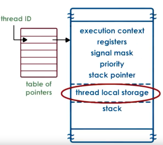
- not POSIX threads, but similar
- thread creation returns thread ID (tid), which is the index into a table of pointers to the actual thread data structure
- stack growth is unbounded -> dangerous! -> red zone -> system error when reaching the red zone
Thread local storage: static variables in thread functions, known at compile time
Size of the data structure is almost known at compile time, so it’s better for locality
Kernel-level Thread Data Structures
It is divided into four parts: process (PCB), light-weight process (LWP), kernel-level-threads (KLT), and CPU. Their context and relationship is shown as below.
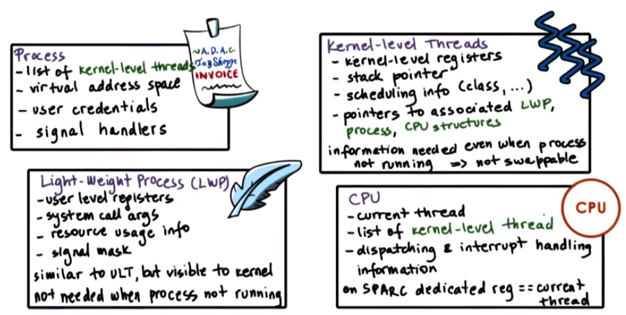
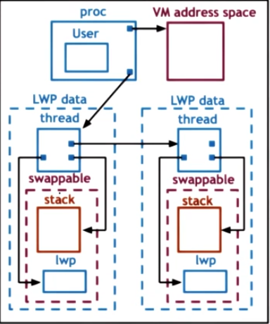
This one doesn’t show the corresponding CPU.
Thread Management
If the ULT and KLT is not visible to each other, it creates overhead between the UL scheduler and KL scheduler. Special system calls must be made to allocate additional KLT, assign UL LWP to it, and release idle KLT after execution is done.
When there are multiple CPUs in the system, interaction is not between UL scheduler, KLT, and CPU. It becomes more complicated.
On multi-CPU system, it may take more time to context switch than spinning CPU cycles for mutex when mutex is held by a thread on another CPU. We call such mutexes “adaptive mutexes”.
When destroying threads, sometimes it is more efficient to reuse them (to avoid allocating memory). When a thread exits,
- put them in a “death row”
- periodically destroyed by a reaper thread
- reuse thread structures and stacks if possible
Interrupt and Signal
Interrupt
- Events generated externally by components other than the CPU (I/O devices ,timers, other CPUs).
- It is delivered to a CPU.
- It is determined by the physical hardware.
- It appears asynchronously.
- It has a unique ID on the hardware.
- It triggers the corresponding handler set for the entire system by OS.
- It can be disabled by interrupt mask.
Interrupt is sent via physical connection to CPU, usually in-band (control signal is sent in the same channel as data signal, compared to out-of-band). It contains the interrupt ID, or MSI (Message Signaled Interrupts).
Interrupt handler table stores handlers of supported interrupts. While the interrupts are system-wide, the handler is defined in the OS.
Interrupts can be directed to any CPU with it enabled. Thus to avoid overheads and perturbations, it makes sense to set interrupt on just a single core.
Signals
- Events triggered by the CPU and software running on it.
- It is determined by the running OS.
- It can appear both synchronously and asynchronously.
- It has a unique ID on OS.
- It triggers the corresponding handler set by process.
- It can be disabled by signal mask.
A signal can be generated when a process/thread accesses kernel-level resources, and other events.
OS provides default handling of signals, if a process doesn’t provide it. Default actions include terminate, ignore, terminate and core dump, stop, or continue.
Process can install handlers via signal() or sigaction() method call. However, some signals cannot be caught by the process.
Example: Synchronous:
- SIGSEGV (access to protected memory)
- SIGFPE (divided by zero)
- SIGKILL (kill by id): can be directed to a specific thread
Asynchronous:
- SIGKILL (kill)
-
SIGALARM
- One-shot signals: n signals pending is equal to 1 pending signal. The handler must be re-enabled after invocation.
- Real time signals: handler is invoked every time the signal is raised.
Handler
Handler operates on the current thread. It will cause implementation difficulties if the handler code is complex. If the handler requires synchronization (acquire locks), then it cannot run on the current thread if the lock is held by the current thread. Instead, it has to run a different thread.
Mask
sequence of 0/1 bits, 0 means disabled and 1 is enabled. If a interrupt/signal is disabled, it will be stored and handled later when it is enabled.
Interrupt masks are per CPU. If mask disables interrupt, the hardware interrupt routing mechanism will not deliver interrupt to CPU.
Signal masks are per execution context (ULT on top of KLT). If mask disables signal, kernel will not deliver it to the corresponding thread.
Thread Performance Considerations
Performance Metrics
Metric matters! When evaludating performance, think carefully about what metric to use.
Metrics: a measurement standard
- measurable and/or quantifiable property
- of the system we are interested in
- can be used to study system behavior
Example:
- wait time
- throughput
- request rate
- execution time
- utilization
- platform efficiency (resources used to achieve certain throughput)
- performance / $, performance / w, etc.
- percentage of SLA violations
Multi-process v.s. Multi-threading
Multi-process: pro: simple programming cons:
- high memory usage
- costly context switch
- hard/costly to maintain shared state
Multi-threading: pros:
- shared address space
- shared state
- cheap context switch
cons:
- not simple implementation
- requires synchronization
- underlying OS should support for threads
Multi-process and multi-thread serves one request per context.
Event-driven model
A dispatch loop continuously checks incoming events, and dispatches them to event handlers. Dispatcher is like a state machine, and call handler is like jump to a specific place in code (not context switch). Handler surrenders control over blocking operations so that other event handlers can be executed.
Many requests interleaved in an execution context. It processes request until waiting is necessary (blocking IO, etc.), then it switches to another request. Thus the number of context switch is minimized.
Multiple CPUs can utilize multiple event-driven processes.
Q: How request dispatcher finds incoming event? Event is input on file descriptor (FD). There is a fixed set of FD to scan through.
APIs to scan FD:
select: allow a program to monitor multiple file descriptors, waiting until one or more of the file descriptors become “ready” for some class of I/O operation (e.g., input possible).poll: performs a similar task toselect. It waits for one of a set of file descriptors to become ready to perform I/O.epoll: performs better thanpoll.
Benefit of event-driven model:
- single address space
- simple flow of control
- smaller memory requirement
- no context switching
- no synchronization
Asynchronous I/O calls
Problem: Blocking I/O calls will block the entire event-driven loop. Use non-blocking, i.e. asynchronous I/O.
- Process/thread makes a system call
- OS obtains all necessary information from stack, and either learns where to return results, or tells caller where to get results later
- Process/thread can continue.
It requires kernel-level thread support (i.e. multi-threaded kernel), and/or device support (e.g. DMA).
Helpers
Q: What if Async calls are not available?
Helpers, threads/processes designed for blocking I/O only. It uses pipe/socket based communication channel with the event dispatcher (select or poll still works), so that the main event loop does not block.
It resolves portability of basic event-driven model where Async I/O is not available, but it has a smaller footprint than regular worker thread design.
Scheduling
CPU scheduler decides when and how processes (and their threads) access shared CPUs.
- chooses one of the ready tasks (from ready queue) to run on CPU
- runs when 1) CPU becomes idle, 2) new task becomes ready, 3) timeslice expired
Two key aspects of scheduler:
- Scheduling algorithm: which task should be executed
- Runqueue: how it is done
Metrics:
- throughput
- average job completion time
- average job wait time
- CPU utilization
Scheduling Algorithm
Run-to-Completion Scheduling
Assumption:
- tasks/jobs that require scheduling are grouped
- known execution times
- no preemption
- single CPU
First-come-first-serve
Algorithm: FIFO Runqueue: normal queue
Shortest Job First
Algorithm: shcedules tasks in order of their execution time Runqueue: priority queue (heap)
Preemptive Scheduling
Estimation of job execution time:
- how long did a task run last time?
- how long did a task run last n times (windowed average)?
Shortest Job First
Preempt longer running jobs (in terms of remaining time) for shorter jobs (just arrived)
Priority Scheduling
Preempt running jobs with lower priority for high priority jobs.
Runqueue: one priority queue for each priority level.
Danger: starvation of low priority tasks. Solution: priority = f(actual priority, time spent in runqueue). The longer a task is in the runqueue, the higher its priority is.
Priority Inversion: if a higher priority task requires mutex held by low-priority tasks, it is executed after the low priority task finishes and releases the mutex. Solution: temporarily boost priority of mutex owner so that it can release mutex sonner.
Round-Robin Scheduling
Pick up the first task from queue. If a task yields because blocking operations like I/O, it is placed at the end of run queue, and the next task in the runqueue is scheduled.
Timeslicing
Each task can run for a maximum amount of time. When the timeslice is expired, the task is returned to the end of runqueue. Tasks may run less than timeslice time (I/O, yield due to priority)
Pros:
- shorter tasks finish sooner
- more responsive
- lengthy I/O operations are initiated sooner
Cons:
- overhead for context switch (thus timeslice » context switch time)
For CPU bound tasks, larger timeslice is better. (context switch overheads are limited, allowing higher CPU utilization on real tasks) For IO bound tasks, smaller timeslice is better. (I/O operations are issued earlier, both CPU and device utilizations are higher)
Runqueue Structure
Use separate queue structure for I/O, mixed, and CPU-bound tasks with different timeslices and priorities.
How to know what type of tasks?
Solution: Multi-Level Feedback Queue (MLFQ)
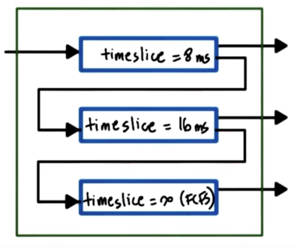
- tasks enter topmost queue
- if a task yields voluntarily before timeslice expires, keep the task at current level; if task uses entire timeslice, push it down to lower level;
- task in lower level gets priority boost when releasing CPU due to I/O waits
Example
Linux O(1) Scheduler
Constant time to select/add task, regardless of task count
Preemptive, priority based: 140 priority level (0-139), 0-99 are real-time, and 100-139 are timesharing. User processes’ default priority is 120, but their “nice value” can be set to -20 to 19 to adjust priority.
Timeslice value depends on priority. Smallest timeslice for lowest priority. Feedback based on waiting/idling: longer sleep time means more interaction with devices, priority - 5 (boost); shorter sleep means compute-intensive, priority + 5 (lowered).
Runqueue is 2 arrays of tasks. Each array element represents a priority level, and points to the first of a list of tasks at this level.
Active array:
- used to pick the next task to run
- constant time to add/select (constant time to detect first non-empty array slot, and indexing with priority)
- tasks remain in queue in active array until timeslice expires
Expired array;
- inactive list
- when no more tasks in active array, swap active and expired array
Problem:
- performance of interactive tasks is poor
- fairness
Linux Completely Fair Scheduler
Runqueue: a single red-black tree (balanced search tree), ordered by “vruntime” (virtual runtime, in nanosec)
Algorithm:
- always pick leftmost node
- periodically adjust vruntime in the runqueue, and compare the current running task to leftmost node. If smaller, continue running; if larger, preempt and place the task back in the tree
- vruntime progress rate depends on priority and niceness: vruntime grow rate is lafster for low-priority
Performance
- select task: O(1)
- add task: O(logN)
Scheduling on Multi-CPU Systems
OS sees CPUs and their cores as entities that it can schedule execution contexts on. Whether it is shared-memory multi-processor (SMP) or multi-core CPU, such system has a shared memory (DRAM), separate last-level cache (LLC) for each CPU/Core, and private on-chip caches for each CPU/Core.
Cache-affinity is important. Schedule a thread to a CPU where its cache is still hot, or keep tasks on the same CPU as much as possible.
Maintain per-CPU runqueue and scheduler, and tasks are load-balanced across CPUs based on per-CPU queue length or when CPU is idle.
If a system has multiple memory nodes, or “Non-Uniform Memory Access (NUMA)”, access to local memory node is faster than that to remote memory node. Tasks should be kept on CPU closer to memory note where there state is, and this is called NUMA-aware scheduling.
Hyperthreading
CPU needs context switching because it has only one set of registers to keep the execution context of a running thread. Hyperthreading provides multiple hardware-supported execution contexts (multiple registers) in one CPU, so that context switching is very fast.
Context switching in Hyperthreading is O(cycles) and memory access is O(100 cycles), hyperthreading can hide memory access latency.
Co-schedule compute- and memory-bound threads on the same core to avoid/limit contention on processor pipeline (compute) and balance out load on memory controller.
CPU-bound or Memory-bound?
Software determination of the characteristics of a thread is not good because of context switching cost. Hardware provides information about a thread via hardware counters:
- Cache misses, L1, L2, LLC misses
- IPC
- Power and energy data
Scheduler can read the hardware counters to estimate what kind of resources a thread needs. Models of well-understood workloads and per-architecture workloads are also used.
Memory Management
OS decouples physical memory from virtual memory space used by processes. Memory management system must be able to allocate memory, replace content in the physical memory with secondary storage, and perform address arbitration such as translation and validation.
Virtual memory is divided into fixed size pages, and physical memory is divided into page frames of the same size. Allocation is done via a mapping from pages to page frames, and arbitration is done via page tables. This is called page-based memory management.
An alternative to page-based management is segment-based memory management. Instead of fixed-size pages, memory is allocated to variable-sized segments.
Hardware support for memory management is provided by Memory Management Unit (MMU). It sits between CPU and main memory that translates virtual to physical addresses, and report faults for illegal access, permission, or content not presented in memory. Special registers are also used to hold pointers to page tables to improve performance. Because VA-to-PA translation happens at every memory access, a cache can be used for valid translations. It is called Translation Lookaside Buffer (TLB). The actual translation is done by hardware.
Page Tables
Page table is a map that tells OS and hardware where to find the virtual memory in physical memory. It’s a mapping between Virtual Page Number (VPN) to Page Frame Number (PFN). There are offsets for each entry to decide the actual location in the page.
To reduce number of entries in page table, consecutive memory space can be combined into one entry. Memory is allocated on first touch, and can be reclaimed if not used. Reclaimed pages have valid bit set to 0. Reaccess will reestablish pages, but it will be in a different PFN.
Note page tables are per-process. Context switch will result in switching to another valid page table. It is done by updating a register (CR3 register in x86) with address to the page table.
Page Table Entries
Each entry has multiple flags besides PFN.
- Present (valid/invalid)
- Dirty (written to)
- Accessed (read or write)
- protection bits: RWX
OS uses flags to determine the validity of access. Faults will be placed onto kernel stack and trap the CPU into kernel mode to handle the fault.
Page Table Size
In 32-bit architecture, Page Table Entry (PTE) is 4 bytes, including PFN and flags. Virtual Page Number (VPN) is \(2^{32}\) / page size. Common page size is 4 KB. So the size of the page table is 4 MB (per process).
In 64-bit architecture, Page Table Entry (PTE) is 8 bytes. If the page size is still 4KB, the page table will be 32 PB.
However, processes don’t use the entire address space, but page table assumes an entry per VPN, regardless of whether the virtual memory is needed or not.
To save space, hierarchical page tables can be used. In a two-level design, outer page table or top page table is page table directory, and internal page table exists only for valid virtual memory regions. On malloc, a new internal page table may be allocated. This is important to 64 bit architectures as memory space contains larger and more sparse gaps.
Translation Lookaside Buffer
Because memory access will require $n$ page table accesses ($n$ is the number of page table levels) and 1 memory access, multi-layer page table can introduce overhead. Modern MMU provides hardware cache for address translation, called Translation Lookaside Buffer (TLB), to improve memory access performance. TLB has all protection/validity bits to validate access.
Small number of cached address can result in high TLB hit rate, due to temporal and spatial locality. For example, x86 Core i7 processor has 64-entry data TLB and 128-entry instruction TLB per core, and 512-entry shared second-level TLB.
Inverted Page Table
Because physical memory space is much smaller compared to virtual memory space, page table can be constructed with only allocated physical memory space. OS maintains a page table with one entry for each physical frame. Each entry contains the Process ID (PID), the first part of the virtual memory, and offset. To look up a memory address, a linear search is performed to find the entry, whose index is the physical frame number.
To speed up lookup, hashing can be used to construct a hashing page table. The logical address is hashed, and the hash value is the entry in the page table.
Segmentation
Segments can be used to represent a contiguous physical memory with arbitrary granularity. It often corresponds with code, heap, data, stack, etc. Logical address is then segment selector and offset.
Segments must be supported by the hardware.
Page Size
Different OS/hardware platform supports different pages sizes. For example, Linux/x86 platform supports 4KB, 2MB (large), and 1GB (huge) page sizes. Large pages can significantly reduce the page table size. But if the page is not fully used, internal fragmentation will occur, which wastes memory.
Memory Allocation
Memory allocator determines VA to PA mapping. It exists at kernel-level as well as user-level. Kernel-level allocator allocates memory for kernel state and static process state. It also tracks the amount of free memory available to the system. User-level allocator manages dynamic process state (heap), and malloc/free operations.
Efficient memory allocation algorithm limits the possibility of external fragmentation (in which free memory space are fragmented and cannot be used by largest allocation request), and permits coalescing/aggregation of free areas.
Linux Allocator
Buddy Allocator
It starts with \(2^x\) area. On allocation request, it subdivides the memory space into \(2^x\) chunks and find the smallest \(2^x\) chunk that can satisfy the request. Fragmentation still exists, but on free it is easy to check to see if neighbors can be aggregated into a larger chunk, so aggregation works well and fast.
Slab Allocator
Internal fragmentation occurs when allocation requests are not close to \(2^x\). Slab allocator builds caches for certain-size objects on top of contiguous memory, so that internal fragmentation can be avoided, and external fragmentation is no longer an issue. Each allocation request will get a space on the cache, or new cache will be created.
Demand Paging
Because virtual memory is much larger than the physical memory, virtual memory page is not always in physical memory, and physical page frame can be saved and restored to/from secondary storage.
Demand paging is the process of having pages swapped in/out of memory and a swap partition (e.g. on disk).
- On a memory access, page table’s present bit indicates the page is not present in memory.
- It traps into OS kernel.
- OS determines the location of the page, and issue an IO request to retrieve the page.
- The missing page is brought back to memory.
- Page table is reset with the new physical memory location.
- Memory access is returned.
if a page is “pinned”, swapping will be disabled.
Page Replacement
When should page be swapped out by page(out) daemon?
- when memory usage is above threshold
- when CPU usage is below threshold
Which pages should be swapped out?
Pick Least-recently used pages. It uses the Access bit to track if page is referenced. Other choices are pages that don’t need to be written out, which can be tracked using the dirty bit.
Other Memory Optimization
Copy-on-Write
MMU can perform other functionalities and optimizations beyond address translation, access tracking, and protection enforcement. One example is copy-on-write (COW).
In some cases, memory copy is required, but data may be identical and unchanged. Thus, on copying, MMU can map new VA to the original page and write protect the original page. However, on write, a page fault is generated and page is copied. In this way, copy cost is only paid if necessary.
Checkpointing
It is a failure and recovery management technique. It periodically saves process state, so that when failure happens, the process can restart from checkpoint (instead of the beginning), so recovery can be much faster.
Memory Debugging
A technique called Rewind-Replay is to rewind to a recent checkpoint and replay memory access from there.
Process Migration
A process can be migrated to another machine for disaster recovery or consolidation purposes. Fast checkpoints are made and copied until a pause-and-copy opportunity becomes available.
Inter-Process Communication
OS-supported mechanisms for interaction among processes. The most common IPC mechanism includes message passing (via sockets, pipes, message queues), and memory-based IPC (shared memory, memory mapped files). IPC can also provide higher-level semantics on the communication protocol, such as files or Remote Procedure Calls (RPC). IPC also provides synchronization primitives.
Message-Base IPC
OS creates and maintains a channel (buffer or FIFO queue) and an interface to processes, called port. Processes send (write) and receive (read) messages from a port. OS kernel establishes communication and perform each IPC operation, this means both send and receive requires a system call and data copy, and a request-response operation invokes 4 user/kernel crossings and 4 data copies.
Thus, while it is simple for processes, the overhead of kernel operations is large.
- Pipes: carry byte stream between 2 processes. For example, a pipe is used to connect the output of a process to the input of another process.
- Message queues: carry “messages” among processes. OS manages priorities, message delivery scheduling, and exposes operations via APIs (SysV “System-Five” or POSIX).
- Sockets: a message queue. The interface is called “socket”, and
send()andrecv()methods pass message through buffers. Kernel associates necessary kernel-level processing to a socket (e.g. TCP/IP). If a socket is used to communicate between different machines, it is a channel between a process and a network device. If used on the same machine, the full protocol stack can be bypassed.
Shared-Memory IPC
Processes read and write to a shared memory region. OS establishes shared channel between the processes by mapping virtual address space for both processes onto the same physical page. Also the physical memory does not have to be contiguous.
System calls are invoked only for setup of the channel, and data copies can be potentially reduced (but not eliminated as processes need to copy memory to separate locations). The disadvantage is that it requires explicit synchronization, communication protocol must be defined in the processes, and management of the shared buffer is in the processes.
Unix and Linux OS supports SysV and POSIX APIs.
Shared memory is organized into “segments”. Segments are not necessarily contiguous physical pages. It is system-wide, and any processes can refer to them. OS limits on the number of segments and the total size of all segments.
The lifecycle of a segment is as follows:
- Create: OS allocates a memory space and assigns a unique key to the segment.
- Attach: processes attach to a segment by referring to its key. OS maps the process’s virtual page to the physical address of the segment.
- Detach: OS invalidates the address mapping in the process’s page table. However, the segment still exists in memory.
- Destroy: OS releases the physical memory of the segment.
Synchronization
Shared-Memory
Accesses to shared state in a single address space by multiple processes must be synchronized. Synchronization mechanism must coordinate number of concurrent accesses to the shared segment, and signal when data is available and ready for consumption.
Mechanisms:
- process threading library (e.g. pthreads). Note synchronization data structures must be shared as well!
- OS-supported IPC for synchronization
Other IPC
Synchronization in message queues can be implemented via send/receive pair. For example, P1 writes data to shared memory and sends ready to the queue; P2 receives the message, reads data from the shared memory and sends OK message back.
Semaphores can also be used. A binary semaphore is like a mutex: when its value is 0, access is blocked; when the value is 1, then decrement (lock) the value and proceed the operation.
IPC Command Line Tools
ipcs: list all IPC facilities.-mdisplays info on shared memory IPC only.ipcrm: delete IPC facility.-m [shmid]deletes shm segment with given ID.
Synchronization Constructs
Spinlock
Spinlock is a basic sync construct like a mutex. It provides mutual exclusion and lock/unlock operations. However, unlike mutex blocks a thread when a lock cannot be acquired, spinlock keeps the thread running in CPU to periodically check whether the lock is released. The thread continues to run until it is preempted.
Spinlock requires hardware support. The check of lock state and acquiring the lock must happen atomically. Such hardware support is atomic instructions. Atomic instructions are hardware specific, and some common operations are test-and-set, read-and-increment, and compare-and-swap. They guarantee atomicity, mutual exclusion, and queueing all concurrent instructions but one. Thus, atomic instructions are used in the critical section with hardware-supported synchronization.
With atomic instruction, spinlock can be implemented as follows:
spinlock_lock(lock):
	while(test_and_set(lock) == busy);
Semaphores
Semaphore is a common sync construct in OS kernels. It is like a traffic light that signals threads to STOP or Go. It is more generalized than mutex.
Semaphore is an integer value. It allows certain number of concurrent access. Upon initialization, it is assigned a max value (a positive integer). On try, if the value is not zero, its value is decremented and access is granted. When its value is zero, it blocks access. On exit, the integer value is incremented.
Reader Writer Locks
Syncing can be done differently based on types of accesses. For example, shared access is granted to read operation, and exclusive access is granted to write operations. A Reader-Writer Lock specifies the type of access and lock behave accordingly.
Rwlock is supported in many platforms, such as Windows (.NET), Java, POSIX, etc. Sometimes it is called shared/exclusive locks. However, there are semantic differences among implementations. For example, different processes can have different priorities, and priorities can be upgraded/downgraded. Also scheduling policy can be implemented on rwlock so that read is blocked if higher priority writer is waiting.
Monitors
Low-level synchronization constructs place the burden of implementing locking and waiting on the developers. It is often error-prone, or inefficient, to use low-level constructs.
Monitor is a high-level construct that helps with this. It specifies a shared resource protected by a synchronization construct, all possible entry procedures, and possible condition variables. On entry, lock and check will be performed automatically by the monitor. Similarly, unlock, check, signal will be performed on exit.
In Java, synchronized methods generate monitor code, but notify() must be called explicitly.
Other Synchronization Constructs
Serializers, path expressions, barriers, rendzvous points, optimistic wait-free sync.
All synchronization constructs require hardware support.
Shared-Memory Multiprocessors
Multiple CPUs access one or more shared memory spaces via a bus (only in-flight one access at a time) or interconnect (only one access to a memory). Such system is called Shared-Memory Multiprocessors, Symmetric Multiprocessors, or simply SMPs. Each CPU has its local cache to hide memory latency, but memory is “further away” from the CPU due to contention.
Write operations to cached memory can have different mechanisms:
- no-write: write operation applies to memory and invalidates the cache;
- write-through: write operation applies to both memory and cache;
- write-back: write operation applies to cache, and write to memory can be delayed.
Cache Coherence
A piece of memory can present in multiple places: one in memory, multiple in caches of different CPUs. Cache coherence is or is not supported by hardware. If cache coherence is done in software, the architecture is called non-cache coherent (NCC); if hardware maintains cache coherence, such architecture is called cache coherent.
Two main cache coherence mechanisms in hardware are write-invalidate and write-update. Write-invalidate invalidates other cache references of a memory space once its updated. The benefit is low memory bandwidth usage (only the memory address is sent over), and potentially cost can be amortized by invalidating once for multiple updates. Write-update updates other cache references when the value is written. The benefit is the update becomes available immediately for other CPU.
Cache Coherence and Atomics
Because it’s difficult to achieve atomicity across multiple caches of multiple CPUs, atomics are always issued to the memory controller. This ensures all references can be ordered and synchronized. But it takes much longer, and generates coherence traffic to all caches regardless of change. Thus, atomic operations are expensive.
Because test_and_set() is expensive, we can add a simple test so that if lock is not free, no atomic operations are issued:
spinlock_lock(lock):
	while(lock == busy OR test_and_set(lock) == busy);
But many threads see the lock is free at the same time, so contention can happen. Delay can be introduced between when lock is free and test_and_set(lock) is issued.
I/O Management
Operating System provides I/O management by:
- Having protocols, i.e. interfaces for device I/O;
- Having dedicated handlers, such as device drivers, interrupt handlers;
- Decoupling I/O details from core processing, so that it abstracts I/O device details from applications.
I/O devices have a lot of variety, including disk, Ethernet/Wifi card, USB devices, GPU, etc. Thus, it is important to identify the key features of I/O devices that enable the integration into the system.
I/O Device Features
Reference, as part of Operating Systems: Three Easy Pieces. An I/O device can be divided into two parts: interface and internals.
Interface provides control registers that OS can access.
- Command
- Data transfers
- Status
Internal components include micro-controller (which is the device’s CPU), on-device memory, and other logic (in hardware-specific chips, such as Analog-Digital Converters).
CPU-Device Interconnect
Device-specific controllers and CPU are connected to an interconnect. Peripheral Component Interconnect, or PCI, is the most common type of such interconnect. Right now the standard is PCI Express (PCIe), which precedes PCI-X (or PCI Extended) and PCI.
Other types of interconnects are SCSI bus, peripheral bus (parallel port or serial port, used to connect keyboard and mouse).
The controller of the device determines which type of interconnect it can directly attach to. There are bridge controllers that can handle different kinds of interconnects.
Device Drivers
OS supports devices via device drivers. This diagram shows how device drivers integrate with OS and the devices:
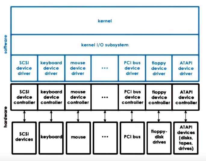
Device drivers are device-specific, so OS must include device drivers for each type. They are responsible for device access, management, and control. They are provided by device manufacturers per OS/version, and each OS provides standardizes interfaces for device drivers. In this way, OS can be independent from devices, and can support a diversity of devices.
Types of Devices
- Block: usually disk devices, it supports read/write blocks of data and direct access to arbitrary block.
- Character: usually keyboards, it supports get/put on a sequence of characters.
- Network devices: between block and character devices, it supports a stream of data in arbitrary sizes.
OS represents a device as a special device file, and read/write operations to these files are translated into device-specific operations. In Unix-like systems, these files are stored in /dev directory, using special file systems such as tmpfs or devfs.
CPU-Device Interactions
CPU accesses device registers in the same way as memory operations. This is called memory-mapped I/O. Therefore, a part of the “host” physical memory is dedicated for device interactions. The memory layout of device registers for each device is stored in “Base Address Registers”.
Another way for CPU to interact with devices is via dedicated in/out instructions for device access, specified in the CPUs ISA. This model is called “I/O port”, because target device is specified in the instruction as an I/O port. The values in device register and data for I/O are also passed in as parameters of the instruction.
The interaction from device to CPU can either via interrupts or CPU polling the device register. As other interrupts, it involves in overheads for interrupt handling steps and cache pollution, but it can be generated as soon as possible. Polling is more convenient for the CPU, but it can either waste CPU cycles or introduces delay.
Programmed I/O
With the basic support from an interconnect such as PCI controller on the device, a system can access or request an operation from a device using Programmed I/O (PIO), without any additional support. It involves CPU to “program” the device by writing into the command registers of the device and control the data movement of the data register.
For example, in a NIC, data register is used for network packets. To send a packet, CPU writes to command register to request packet transmission, and copy packet to data registers as many times as necessary until the whole packet is sent. It looks like a series of store operations from the CPU because device registers are mapped to the memory.
Direct Memory Access (DMA)
The DMA controller provides a different way of moving data to/from the device. With DMA controller, CPU still programs the device by writing to the command register, but the data is sent via DMA controller. The opposite path from device to CPU can be done via DMA controller as well.
For the same example of a NIC, CPU writes to command register to request packet transmission, but then configures the DMA controller with the in-memory address and the size of the packet buffer. From the CPU’s perspective, it requires only one store operation and one DMA configure, but DMA configure is more complex and can take more cycles.
Note that for DMA, the data buffer must be in the physical memory until transfer completes. This means the memory area must be pinned and not swappable.
Typical Device Access
A typical device access involves the following steps:
- The user process issues a system call to perform the device access;
- The kernel performs the necessary operations in preparation of this operation. This is often referred as in-kernel stack.
- The kernel invokes the driver.
- The driver configures the device with this request.
- Device performs the request.
- Any response will traverse back through the call chain to the user process.
OS Bypass
For some devices, the device registers and data are directly accessible from the user space, thus OS configurations can be out of the way. This is referred as OS bypass. This requires the device driver to be made available at user level, i.e. as a library.
However, OS still maintains some coarse-grain control of the device, such as device status, permission, etc. This relies on the device to provide sufficient registers for kernel and user separately. And in order to support multiple processes having access to the device simultaneously, the device must have demultiplex capability to send the data arriving at the device to the right process.
Sync vs. Async Access
For synchronous I/O operations, the user process blocks until the operation is complete. For asynchronous I/O operations, the process continues after the I/O operation is issued, and it can either periodically checks and retrieves the result from the I/O operation, or it is notified that the operation is completed and the results are ready.
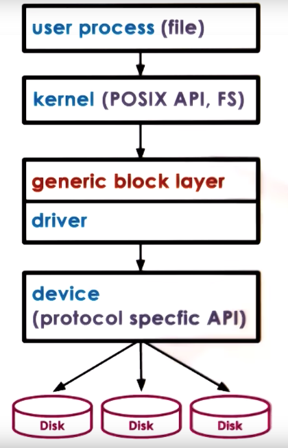
Block Device Stack
Block devices are typically used to store files, a logical storage unit introduced by the the OS through file system and used by processes.
Kernel file system defines where, and how to find and access file. OS specifies an interface, such as POSIX API, for multiple file systems to abstract away the underlying file system from user processes.
There can be multiple types of block devices, each with protocol-specific APIs. To abstract them, there is usually a “generic block layer” between the kernel and the device driver, which is an OS-standardized block interface. It will resolve the “generic” read/write operations from the kernel to those for a specific block device type.
Virtual File System
To address the following scenarios:
- files are on more than one device;
- devices work better with different file system implementations;
- files are not on a local device (such as network attached storage);
OS like Linux uses a virtual file system layer. The virtual file system hides the underlying file system from the user layer so that user processes access a single file system using the same API, and the virtual file system handles the translation to the underlying file system.
Virtual file system provides the following abstractions:
- file: elements on which the VFS operates;
- file descriptor: OS representation of a file, and operations, such as open, read, write, send file, lock, or close, are defined on file descriptors.
- inode: a persistent data structure of the file “index”, including a list of all data blocks (index node of a file), device, permissions, size, etc.
- dentry (directory entry): corresponds to a single path component being traversed to reach a particular file. For example, directory
/users/baihuconsists of/,/users, and/users/baihudentries. - superblock: file system-specific information regarding the layout of the file system.
Thus, these abstractions are persisted on the disk as follows:
- file: a number of blocks;
- inode: tracks file’s blocks, and also resides on the disk in some blocks;
- superblock: overall map of the disk blocks, so that the OS can tell the content of each block to be inode/data/free block. This is used for allocation and block lookup.
Inode
Inode is the index of all disk blocks corresponding to a file, and a file is identified by an inode. Inode contains a list of all data blocks in a sequential manner. This allows easy access both sequentially and randomly, but it puts a limit on the file size. For example, for 128 Bytes inode, with 4 Byte block pointer, it allows 32 addressable blocks. If each block is 1 KB, then the maximum file size is 32 KB.
One way to overcome this file limit is to have indirect pointers, that points to blocks of pointers. Each block of pointers can support 256KB per entry (1KB/4B = 256 entries). It can also have double indirect pointers (pointers of pointers), triple indirect pointers, etc. The benefit of indirect pointers is to support large file size with small inode, but the access to the file slows down with multiple disk accesses.
ext2: Second Extended File System
It was a common file system in Linux, and was superseded by ext3 and then ext2.
The first block is often not used by Linux, it is used to boot up the computer. The rest of the disks are organized into a series of block groups. Each block group is as follows from the start to the end:
- superblock: number of inodes, number of disk blocks, and the start of free blocks
- group descriptor: the location of bitmaps, number of free nodes, and number of free directories (because ext2 tries to balance it across block groups);
- bitmaps (for data blocks and inodes): tracks free blocks and inodes;
- inodes: numbered from 1 to a max number, each of 128 Bytes and describes exactly one file;
- data blocks: file data.
Reducing File Access Overheads
OS supports multiple mechanisms to reduce file access overheads.
Caching/buffering in memory is to reduce number of disk accesses.
- Buffer cache presents in main memory
- Read/write happens from cache
- OS periodically flushes cache to disk via the
fsync()system call..
I/O scheduling is to reduce disk head movement by maximizing sequential access over random access.
Prefetching is to increase cache hits by leveraging locality. This is to fetch subsequent blocks when a block is read and cache them in main memory.
Journaling/logging is to reduce random access but ensure no losses of data (as I/O scheduling would result in loss of data). It “describes” write operations in log in a sequential manner, such as block ,offset, value, etc. and then periodically apply them to proper disk locations. Ext3 and ext4 uses journaling.
Virtualization
It originates at IBM in the 1960s, virtualization allows concurrent execution of multiple OSs (and their applications) on the same physical machine. Each OS thinks that it “owns” hardware resources through virtual resources. A virtual machine (VM), or guest, is the OS, its applications and its virtual resources. And the virtualization layer, including virtual machine monitor or hypervisor, manages the physical hardware and provide isolation to guests.
A virtual machine is an efficient, isolated duplicate of the real machine. It is supported by a virtual machine monitor (HMM), which provides:
- fidelity: provides environment essentially identical with the original machine.
- performance: programs show at worst only minor decrease in speed compared to a physical machine with the same hardware.
- safety and isolation: VMM is in complete control of system resources, and policies to resources cannot be altered by guests.
The benefits of virtualization include:
- Consolidation: decrease cost, improve manageability;
- Migration: availability and reliability. VMs can be migrated from physical hardware to another, or pause and clone.
- Security;
- Easy to debug;
- Support for legacy OSs.
Two Main Virtualization Models
There are two main models of virtualization:
- Bare-metal or hypervisor-based (type 1);
- Hosted (type 2).
In bare-metal model, VMM (hypervisor) manages all hardware resources and supports execution of VMs, but this requires hardware manufacturers to provide device drivers to all types of hypervisors. To address this, one way is to run a privileged, service VM on top of VMM to deal with devices, and other configuration and management tasks. This model is adopted by Xen (open-source or Citrix XenServer) and ESX (VMware). In Xen, the service (or privileged) VM is called dom0 and guest VMs are called domUs. By definition, device drivers runs in dom0. ESX targets mainly server markets, which have fewer types of devices. Because of VMware’s market share, it mandates vendors to provide drivers for its VMM, and it runs drivers in VMM. ESX provides many open APIs for management and configuration. It used to have Linux-based control core (service VM), but now it provides remote APIs to configure VMM.
In hosted model, there is a normal OS called host OS, which owns all the physical hardware and runs all device drivers. The host OS runs a VMM module that provides hardware interfaces to VMs and deals with VM context switching. Because the host OS is a normal OS, native applications can be run in it along with guest VMs. One example of hosted model is KVM (kernel-based VM) based on Linux. KVM achieves virtualization by a combination of the KVM kernel module in the host Linux OS and QEMU for hardware virtualization, which exposes emulated hardware to guest VMs.
Hardware Protection levels
Commodity hardware has more than 2 protection levels. For example, x86 has 4 protection levels (rings): ring 0 provides the highest privilege (and OS runs in ring 0); ring 3 runs applications with the least privilege. In virtualization, ring 0 runs the hypervisor, ring 1 runs the guest OSs, and ring 3 runs applications. Recent x86 architecture introduces 2 protection modes, root and non-root. Then hypervisor runs in ring 0 of root mode, and VMs run in non-root mode (in which certain operations are not allowed) with OSs run in ring 0 and applications run in ring 3.
Attempts by the guest OS to run privileged operations cause traps called VMexit which triggers the switch and passes the control to hypervisor. When the operation completes, VMenter is triggered to enter non-root mode.
Processor Virtualization
To achieve great efficiency, guest instructions are executed directly by the hardware. Non-privileged operations run at hardware speed to achieve efficiency, and privileged operations trap to the hypervisor. Hypervisor determines whether the attempts of privileged operations are legal. If not, then the VM is terminated; if so, it emulates the behavior the guest OS expects from the hardware. This trap-and-emulate is key to achieve efficiency in processor virtualization.
However, before 2005, x86 does not provide protection modes, causing issues with trap-and-emulate. There are 17 privileged operations that cannot be issued from other than ring 0 and are failed silently. In other words, guest OSs (in ring 1) assumes operations are successful, but hypervisor does not receive trap and thus performs no operations.
There are two ways of address this issue, binary translation and paravirtualization.
The goal for binary translation is to achieve full virtualization, that guest OSs can run in the virtualized environment without any modification. Binary translation dynamically rewrites the VM binary to never issue those 17 instructions.
- Capture and inspect code blocks that is to be executed.
- If needed, translate to alternate instruction sequence, e.g. to emulate desired behavior possibly even avoiding trap.
- Otherwise, run them at hardware speed.
Generally, binary translation has overheads. But overheads can be amortized by caching translated blocks.
The goal of paravirtualization is to achieve high performance by giving up unmodified guests. Guest OSs are modified so that:
- it knows that it is running in a virtualized environment;
- it makes explicit calls to the hypervisor (hypercalls) instead of direct hardware manipulations.
- Hypercall is similar to system call, which packages context information in the guest OS, specifies desired hypercall, and traps to VMM.
Paravirtualization originates from the Xen hypervisor.
Memory Virtualization
In full virtualization, all guests expect contiguous physical memory starting at 0. There are three notions of memory: virtual (application memory space), physical (address space of a guest OS), and machine. Both addresses and page frame numbers must be translated. Note that hypervisor still leverages hardware features such as MMU and TLB. One option is that guest OSs continues to map virtual memory to physical memory, hypervisor must map physical memory for each guest OS to the machine memory. This option is too expensive as every memory operation must be translated twice. Another option is for hypervisor to maintain a shadow page table between the virtual memory to the machine memory. This requires hypervisor to maintain consistency such as to invalidate on context switch, write-protects guest page table to track new mappings.
In paravirtualization, guest OS no longer strictly requires contiguous physical memory space starting at 0. It can explicitly registers page tables with the hypervisor, so that there is only one level of memory mapping. The guest OS can “batch” page table updates to reduce VM exits to amortized cost and improve performance.
Device Virtualization
For CPUs and memory, there is less diversity because of the existence of ISA. However, devices are of high diversity with lack of standard specification of device interface and behavior. There are three models.
In the passthrough model, the VMM-level driver configures device access permissions. VMs are provided with exclusive access to the device and it can directly access the device (and this is why this model is also called VMM-bypass). But the disadvantages are significant:
- device sharing is difficult;
- VMM must have exact type of device as what VM expects;
- VM migration is tricky because device states in guest OSs are maintained by hypervisors and must be copied over during migration.
In Hypervisor-direct model, VMM intercepts all devices accesses, and emulate device operations by translating the operation to generic I/O operations and traversing it through VMM-resident I/O stack, and invoking VMM-resident driver. The advantage of this model is that VMs are decoupled from physical devices, resulting in ease of sharing, migration, and dealing with device specifications. The disadvantage is it adds latency to device operations, and hypervisor is now exposed to the complexity of all device drivers.
In split-device driver model, device access control is split between two drivers: front-end driver in guest VMs that provides device API, and back-end driver in service VM or host, which should be stock device driver for the service/host OS. The front-end driver must be modified to pass device operations to the back-end driver, limiting it to paravirtualized guests. The advantage is that it eliminates emulation overhead, and allows for better management of shared devices.
Hardware Virtualization
AMD Pacifica and Intel Vanderpool Technology (Intel-VT) started to add hardware support for virtualization around 2005.
- It fixed the “holes” in the x86 ISA by correctly trapping the 17 instructions during virtualization.
- It introduced root/non-root mode (or host/guest mode) as additional protection.
- It supports the VM control structure so that the hardware understands the state of the virtualized processor, or vCPU, to reduce virtualization overhead.
- It improves memory management by supporting extended page tables and tagged TLB with VM ids.
- Additional support in the hardware such as multi-queue devices (devices with multiple logical interfaces to different VMs) and interrupt routing which interrupts the core where the corresponding VM runs.
- Security and management support.
These features are achieved by additional instructions to x86 ISA.
Remote Procedure Calls
Inter-process communication is a mechanism to move data between address spaces. It is a low-level mechanism and it does not specify the protocol for data exchange. Among different applications, there are common steps related to remote IPC, which is captured by remote procedure calls.
RPC is intended to simplify the development of cross-address space and cross-machine interactions. It provides benefits such as:
- High-level interface for data movement and communication;
- Error handling;
- Hiding complexities of cross-machine interactions from applications.
RPC requires:
- Interactions between two processes follow client-server model;
- Follows the procedure call interface, i.e. synchronous-call semantics. This is because when RPC is proposed, the programming languages are procedural languages.
- Performs type checking. It provides error handling and bytes interpretation.
- Cross-machine conversion such big/small endian, floating points, negative numbers;
- Provides higher-level protocol such as access control and fault tolerance.
An RPC call contains the following steps:
- register: server “registers” the supported procedure, argument types, its location, so that clients can discover it.
- bind: client finds and “binds” to the desired server. For a TCP-based protocol it involves the creation of a connection.
- call: client makes a RPC call. The control is passed to the client stub and client code blocks.
- marshal: client stub “marshals” arguments (serialize arguments, which is distributed in the client’s memory space) into a buffer.
- send: client stub sends the message to the server.
- receive: server receives the message, performs optional access control, and passes the message to the server stub.
- unmarshal: server stub “unmarshals” arguments by extracting arguments from the message and create structs in the local memory.
- actual call: server stub calls the local procedure implementation.
- result: server performs the operation and computes the result of the RPC implementation.
- return: it performs similar steps to return the result back to the client.
Interface Definition Language
Client and server can be developed independently with different languages and requires the interface to be defined. An Interface Definition Language (IDL) is used to describe the interface a server exports:
- procedure name, argument and return types;
- version number.
Version number is required so that the server and client can be upgraded separately.
IDL can be language agnostic (such as XDR in SunRPC) or language specific (such as Java in Java RMI). Note that the IDL language is only used by the RPC system to generate stubs, perform discovery, etc. It does not dictate the actual implementation.
Marshalling and Unmarshalling
When an RPC call is made on the client side, variables in the client application’s memory space is passed to it as arguments, and they are not continuous in the memory. However, at the lowest level, a send() call is issued to the socket to send the message across the network, and the send call requires a buffer of continuous memory. The marshalling code will create a buffer, copy arguments from various memory locations into the buffer, as well as other supporting information such as operation name, size of the argument, etc., using a pre-defined structure. It also performs encoding if necessary.
Unmarshalling performs the opposite operation. It decodes the message, extracts arguments from the message and allocate them into the local memory space, in preparation for invoking the implementation of the RPC call.
Note that marshal/unmarshal routes are provided by the RPC system compiler that generates the code from IDL to a specific language.
One tricky issue is the usage of pointers. RPC protocol can either prohibit the usage of pointers, or implement marshalling/unmarshalling for pointers so that the referenced data structure is included in the buffer.
Binding and Registry
During the binding step, client determines which server it should connect to based on the service name, version number, etc., and how to connect to the server, based on IP address, transport protocol, etc. The client requires information of available servers to perform binding.
A registry is a database of services available to a client. It includes service names and connection details so that client can perform binding. Registry can be distributed for any RPC service to register, or machine-specific so that only local clients or clients that know the machine address to query them.
Error Handling
There are a lot of ways that an RPC call can fail. RPC provides special notification, such as signal or exception that catches all possible ways in which an RPC call can (partially) fail and signal the client application of possible failures.
Encoding
Besides the actual data of the RPC, arguments or results, being encoded into a bytestream depending on the data type, there are other data fields encoded into the actual data buffer.
- RPC header: service procedure ID, version number, request ID, etc.
- Transport header: TCP, UDP, etc.
Distributed File System
With the help of Virtual File System, the file system can be on a different machine in the network. Distributed File System includes:
- Client/server model where the file system is on one machine and the client that accesses the file system is on another machine;
- File server is distributed on multiple machines.
- Files can be replicated and each server has all files for better redundancy;
- Files can be partitioned and each server has part of files for better scalability.
- Files are stored on and served from all machines, which act like peers. This blurs the distinction between clients and servers.
Operations on the file system can be split between the client (locally) and the server (remotely). One extreme is all operations are done locally. This is used in FTP, SVN, etc. The benefit is that reads/writes are done locally, but the entire file must be downloaded/uploaded even for small access, and server gives up the control, limiting the possibility of concurrent operations.
Another extreme is true remote access. Every operation is done remotely. The benefit is that file accesses are done in a centralized manner so it is easy to reason about consistency, but every operation pays the network cost, and the load on the server is much higher, limiting the scalability of the server.
A more practical design is something in between:
- Allow clients to cache parts (blocks) of files locally, to achieve low latency on file operations and reduced server load (and thus higher server scalability).
- Force clients to interact with server frequently. Server understands what clients are doing and has control into which accesses can be permitted, thus consistency management is easy.
However, the server becomes more complicated and file sharing semantics must be defined between client and server. In addition, server now becomes stateful as it must maintain state of client operations, and client requires cache coherence mechanisms.
File Sharing Semantics
- Unix Semantics: every write becomes visible to everyone immediately;
- Session Semantics (one session is time between
openandclose):- Write-back content on
close, and update content onopen(i.e. flush local cache and load from file system); - It is easy to reason about, but may be insufficient due to long delay of changes.
- Write-back content on
- Periodic Updates:
- Client writes back periodically, as if it has a “lease” on its cached data (not exclusive);
- Server invalidates client’s cache periodically, providing an upper bound of period of inconsistency;
- These can be achieved by the augmented
flushandsyncAPI.
- Immutable files: never modify, new files are created instead.
- Transaction: all changes are made atomically.
It is important to understand the access pattern before choosing the semantics. For example, files and directories have very different access patterns, and thus it is not uncommon to choose different semantics for each of them.
Replication and Partitioning
If the file server contains multiple machines, replication and partitioning can be used to organize these machines.
Replication is for each machine to host all files. It supports load balancing and has higher availability and fault-tolerant. However, the writes become more complex as either a write operations must be performed on all machines, or writes must be propagated through the system. In addition, writes must be reconciled, which is a classic problem in distributed system.
Partitioning is for each machine to host a portion of files. It provides better availability compared to a single-machine DFS, higher scalability regarding the file system size, and simpler writes. However, failure handling and load balancing becomes more complex.
Replication and partitioning can be used together to achieve desired performance profile.
Distributed Shared Memory
This section focuses on distributed state management and design alternatives.
In the previous discussion on Distributed File System the client-server model is used, in which clients send requests to file service and servers own and manage states and provide services. This section the “peer” model is discussed, in which each node “owns” state and provides service, and potentially send requests to each other.
One concrete example of “peer” distributed system is distributed shared memory, which maintains shared memory across multiple machines and provides a unified view of shared memory to applications, just like in SMP. Each node owns state (memory) and provides service (memory reads/writes from any node). Distributed shared memory permits scaling beyond the memory limit of a single machine, providing more “shared” memory at a lower cost. The disadvantage is the slower overall memory access, but with the help of commodity interconnect technologies, Remote DMA (RDMA) is supported to achieve very low latency.
Hardware-supported DSM relies on the interconnect, so that the NIC is involved in all aspects of memory management and translates remove memory operations accesses into messages, while OS manages the larger physical memory across all machines.
Design Considerations: Sharing Granularity
In SMP, memory operations are performed at cache line granularity. However, the overhead would be too high for DSM. Some alternative granularities are variable, page, or object (defined by programming languages) level.
- Variable is too small, too, as the smallest unit of a variable is only a few bytes in most languages.
- OS manages memory by page, so it makes sense to support OS-level DSM at page level.
- Object granularity can be supported by language runtime.
As the granularity of sharing increases, the probability of so-called “false sharing” increases as well. False sharing occurs when two concurrent operations happen on two independent memory locations that can be issued concurrently, but due to the memory location, they have to be issued sequentially.
Design Considerations: Access Algorithm
Understanding the access algorithm is equivalent to understanding the applications that use DSM.
- Single Reader/Single Writer (SRSW): DSM only supplies the capability of accessing remote memory;
- Multiple Readers/Single Writer (MRSW)
- Multiple Readers/Multiple Writers (MRMW)
Design Considerations: Performance
The performance metric of a DSM is the access latency. Migration and Replication can be used to achieve low latency. Migration improves memory locality but requires data movement, and replication (or caching) requires consistency management.
Design Considerations: Consistency Management
In SMP, write-invalidate and write-update are used to maintain consistency. However, such operations are performed on every write operation and thus the overhead is too high for DSM. Thus, we look to the consistency mechanisms discussed in DFS.
There are two main ways:
- Push invalidations upon written.
- Pull modifications info periodically or on-demand.
But when these methods get triggered depends on the consistency model of the shared state.
DSM Architecture
A DSM system consists of multiple distributed nodes, each contributes a portion of its own main memory to the DSM. Other local memory can be used for caching, replication, or metadata. The global shared memory space consists of pool of pages from all notes, and every address in this memory space can be uniquely identified by the ID of the machine and page frame number.
If Multiple Readers/Multiple Writers (MRMW) is supported, local cache is required to improve performance. The home node, the node where the page is physically located, or the manager node, drives the coherent operations. All nodes are responsible for part of the state management of the distributed memory.
To manage the state, the home node should keep the state of its pages: pages accessed/modified, cache enabled/disabled, locked, etc. However, every operation will require communication to the home node. Another way is to designate an “owner” for a memory page among nodes with the page cached, and the owner can be different from the home node. The owner can drive the state update and consistency operations. Then home node manages accesses and track page ownership instead.
In addition, instead of caching, pages can be replicated for load balancing, performance improvement, and reliability.
Indexing of Distributed State
The address of a page in a DSM consists of the node ID and the physical page frame number, so each node knows the home node for all pages. Another way is to have a global map between page ID and manager node ID and replicate it across all nodes. But the metadata for each page is located on the manager node. In other words, metadata for local pages are partitioned.
DSM Implementation
DSM must intercept accesses to DSM state in order to 1) send remote messages requesting access, and 2) to trigger coherence messages. However, such overhead should be avoided for local, non-shared pages. OS thus must dynamically engage and disengage DSM when necessary. This is achieved by hardware MMU support, which traps and passes control to DSM when remote address or cached content are accessed.
In addition, other MMU information, such as dirty page, is useful when implementing DSM.
Consistency Model
Consistency Model is the agreement between the state of the distributed system and the software systems that access it. In terms of DSM, it means memory (state) guarantees to behave correctly if access ordering and propagation of updates are done in a pre-defined way.
- Strict consistency: updates visible everywhere immediately. In a single SMP, there’s no guarantee of strict consistency without extra locking and synchronization. In distributed systems, latency and message reorder and loss make this impossible to guarantee.
- Sequential consistency: memory updates from different processors may be arbitrarily interleaved, but all processes will see the same interleaving. But operations from the same process always appear in order they were issued.
- Causal consistency: if writes are causally related (subsequent writes depend on previous writes to be observed), they are guaranteed to be ordered. But there is no guarantee on unrelated, or “concurrent” writes.
- Weak consistency: synchronization points, an operation made available to call, so that all updates prior to a synchronization point will be visible but there is no guarantee to what happens in between. In order for a write operation guaranteed to be visible to a reader, the writer and reader must both perform synchronization. There are other variations to this, such as separate sync per subset of states, or separate “entry/acquire” (sync changes made by others) and “exit/release” (sync others with changes made by the current process) operations.
Data Center Technologies
Internet Services Architecture
Internet Services refer to any type of services provided via a web interface. It can be divided in to three parts:
- presentation: static content
- business logic: dynamic content
- database tier: data store.
There may be a middleware layer, which are supporting, integrative, or value-added software technologies.
They are not necessarily separate processes on separate machines. In multi-process configurations, some form of IPC is used, including RPC, shared memory, etc.
To provide Internet services at scale, applications must be multi-process, multi-node, in a “scale-out” architecture. For example,
- Boss-worker: front-end distributes requests to worker nodes;
- All equal: all nodes execute any possible step in request processing for any request;
- Specialized nodes: some nodes execute some specific step(s) in request processing for some request types.
They can be classified as homogeneous or heterogeneous architectures.
Cloud Computing
The traditional IT approach is to buy and configure resources by determining capacity based on expected, peak demand. Cloud computing can provide:
- on-demand, elastic resources (infrastructure) and services (software);
- fine-grained pricing based on usage;
- professionally managed and hosted;
- API-based access.
Customers of cloud computing pay a fee. The billing service comes with many models (spot, reservation) at discrete quantities (small, medium, large).
The business of Cloud Computing benefits from two facts:
- The law of large numbers: the computing demand from many customers are roughly constant.
- Economy at scale: buying resources at bulk is cheaper compared to individual customers.
Cloud can be classified as public or private based on its deployment model:
- public: third-party customers/tenants;
- private: leverage the cloud technology internally;
- hybrid: public + private, public resources are used for failover, dealing with spikes, or testing;
- community: a type of public cloud used by certain type of users (instead of arbitrary users).
Cloud can also be classified based on services:
- on-premises: everything is managed in house;
- Infrastructure: everything below OS is managed by the cloud provider;
- Platform: application and data is managed by user, and runtime environment and below are managed by provider;
- Software: everything is managed by the provider.
Requirements for the cloud provider are:
- Resources must be “fungible”, meaning they can be easily reprovisioned for a different customer or a different purpose;
- Elastic, dynamic resource allocation methods;
- Operate at scale;
- Dealing with failures;
- Provide performance and isolation in a multi-tenant environment;
- Security.
Cloud-enabling technologies include:
- Virtualization;
- Resource provisioning and scheduling;
- Software-defined networking, storage, data centers;
- Big data storage and processing, distributed file system, NoSQL database, distributed in-memory caches;
- Monitoring and real-time log processing.