In Extend WiFi Coverage with Multiple APs post, I discussed some considerations of setting up multiple access points (AP) and helping clients roam across them. However, it is more important to have sufficient signal coverage in all rooms. We would like to achieve the best coverage with minimum number of devices. In the end, network devices are not cheap! Thus, placing APs in the correct locations is paramount.
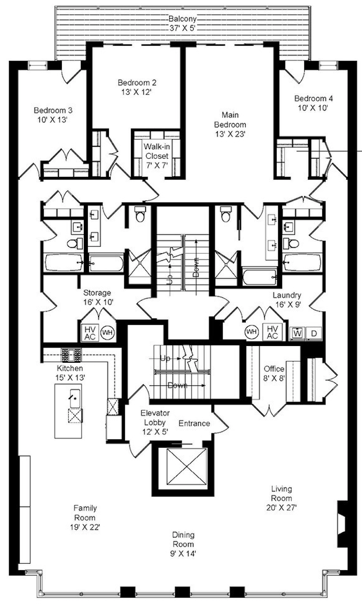
This post demonstrates how to use UniFi Design Center to design the placement of APs for optimal coverage from a floor plan. I personally find it very accurate and helpful not only for new deployments but to troubleshoot signal strength issues in existing deployments without being on site and performing signal measurement. For demonstration purposes, I’ll use the following penthouse (not my property) as example.
To begin, log in to UniFi Design Center with your Ubiquiti account. Create an account if you don’t have one. Then create a project and upload the floor plan to this project.
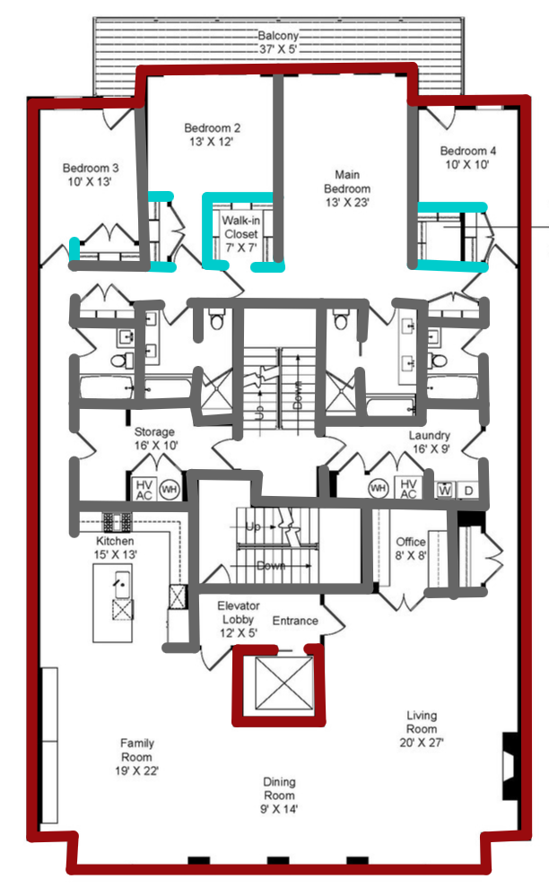
As WiFi signals attenuates through walls, it is important to mark the location and the materials of walls on the floor plan. The “Builder” tab allows drawing of outer (brick or concrete), inner (wood or drywall), and divider walls. So the first step is to mark all the walls on the floor plan, which then looks like this:
Second, though not relevant to the WiFi signal, we should add a router and switches so APs can be connected to the network. For small- or medium-sized projects, I prefer to use a UniFi Dream Machine, which is a Security Gateway, a 4-port switch, a cloud key (that runs UniFi controller), and an AP in one unit, or EdgeRouter X as I previously discussed in the Device and Management Setup post. Given this is a large property, I throw a UniFi Dream Machine Pro and two 24 Port POE switches (for redundancy) on a server rack in the storage room.
Then the fun part begins. Enable the signal strength coverage map and start placing APs onto the floor plan! For this post, I’m using ceiling-mount UniFi AP HD in large rooms and hallways, and UniFi HD In-Wall to provide both wireless and Ethernet ports to bedrooms.
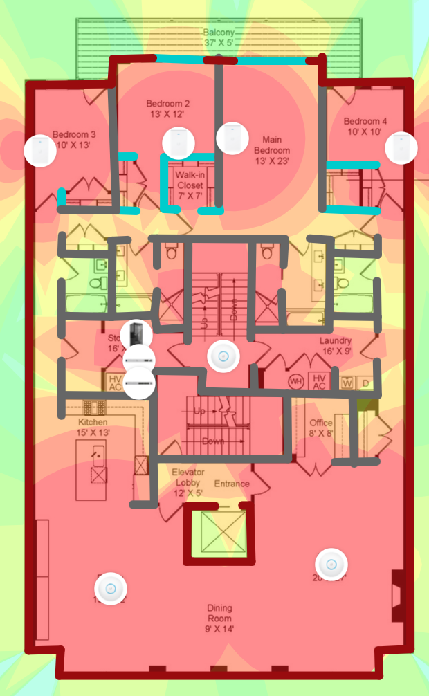
As you can see, it provides excellent 5 GHz signal coverage to all rooms. We also want Ethernet wall sockets to other rooms, and you can place them onto the floor plan too.
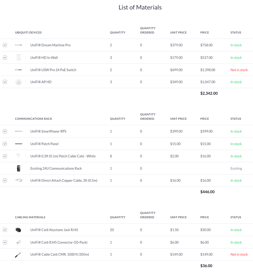
Lastly, we should wire them up. The Design Center provides auto-cabling that connects everything together, and calculates number of ports, PoE power, and number of rack slots used in this design. The final design looks like this:
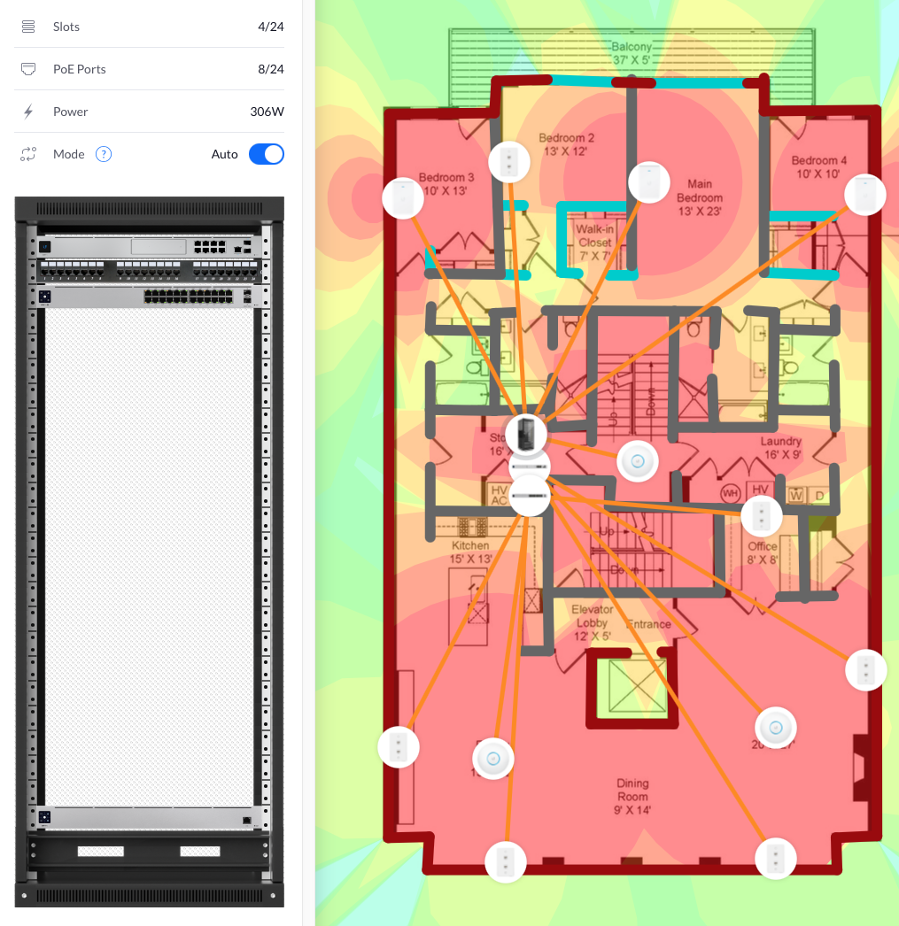
It does not use cable route so the length of cabling required is underestimated. But it does a great job of calculating the number of network devices used and the total cost to help you make a cost-aware decision about the design.
Of course, this is the “ideal” design, which uses an excessive number of top-end APs to provide excellent 5 GHz WiFi coverage too all rooms. In a more realistic deployment, we can have a decent coverage with fewer APs. In addition, access to Ethernet ports for placing APs may not be possible for existing properties not under renovation, and you will have to accommodate for this limitation if installation of new cables is not possible or cost-prohibitive.
I have used this tool to design the wireless network for a new property and diagnose the WiFi dead spot in my existing place. Both cases it provides great insights into what APs I should get and where to place them. You can try out different types of APs and configurations and get instant simulation of the wireless environment, so you can have a solid design before purchasing any devices.
Further Reads
This is the post series. Other posts can be found under HomeNetwork tag.